“Editor’s Note: Due to the popularity of some of eHam’s older articles, many of which you may not have read, the eHam.net team has decided to rerun some of the best articles that we have received since eHam’s inception. These articles will be reprinted to add to the quality of eHam’s content and in a show of appreciation to the authors of these articles.” This article was originally published on: 12/05/2002
K0FF’s Homebrew Tips:The 2 meter Square Copper Dipole by K0FF
Originally published and copyright by K0FF 5 Dec 2000 on eHam

Construction Detail
Here is the parts list and dimension sheet for a 2m square dipole, made from copper plumbing fittings and 1/2 inch copper water pipe.
It is more or less omni-directional, and horizontally polarized. You can even make it from the short pieces of pipe left over from the 6M project (see eHam how-to article “6 Meter Square Copper Dipole by K0FF”).
The antenna presents a low-through-high angle of takeoff, and is intended for use in the 144.200 area, although it’s wide enough to use as an AO-27 uplink, and can handle 100W. It’s particularly useful on AO-27 when the pass is very high or overhead, and in the “cone of silence” of a fixed vertical. I use this for mobile satellite uplink, and wave a short hand-held 430 antenna out the window for receive. Excellent results from SSB mobile too, where I’ve been able to talk to other mobiles similarly equipped 200 miles away. The mounting arrangement allows it to be affixed to a standard mobile mast that presents a 3/8 x 24 male thread (ALA Hustler base mast). You run coaxial cable right to the antenna and connect it to the built in SO-239.
The only adjustment on it is the Gamma match, as the design dimensions set resonance. You may want to adjust the final SWR by sliding the end caps in or out before soldering them.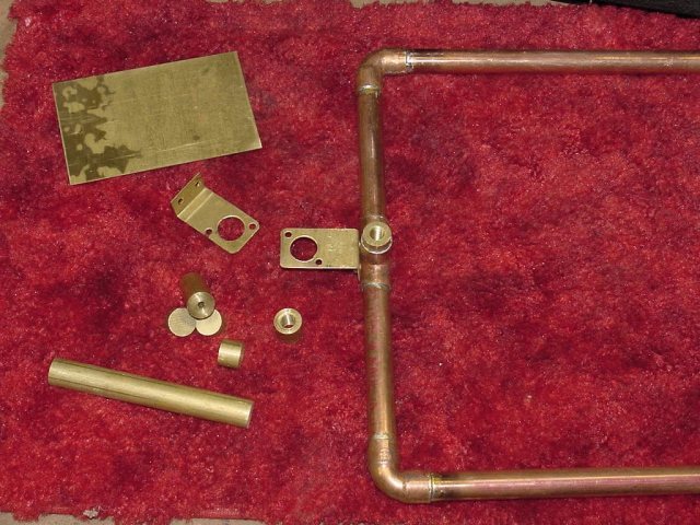 Brass Parts
It’s just a dipole folded around on itself.
The shape is an open 11 inches with mounting via a copper TEE with the open end down. In that open end solder a 1/2″ brass rod, which has been drilled and tapped for 3/8-24.
For stacking a pair, you could make the TEE and threaded insert come horizontally instead, and mount one antenna above the other. (Future articles will give detailed info on stacking antennas in general). Stacked antennas provide improved gain and power handling capabilities.
Side mounting on a tower can be achieved by using conduit clip large enough to go around the mast (or tower leg), and run a 3/8 x 24 s.s. bolt into the threaded fitting.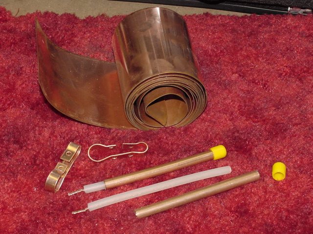 Copper Parts
Solder the antenna parts together per the drawing using the 90 degree elbows at the corners. Cap the far (open) ends and mind the gap. All measurements are critical. The brass plate* to hold the SO-239 is bent to form an “L” 1-3/4″ tall with a 1/2″ lip. A 5/8 hole is provided 1-1/4 inch from the bend, and the SO-239 is attached using stainless steel or brass hardware*. Two small holes are drilled in the lip and the plate is mounted to the copper TEE with #6 s.s. Self-taping screws*. Solder a ring lug* to the center conductor of an 11″ piece of RG8 insides* and screw it into the threaded coupling* on the SO-239 *(center wire and plastic dielectric only- remove and discard shield and outer covering). Slip the RG8 insides into the 3/8″ copper tube* 4-1/2″, and tap the copper tube to the radiating element 3-1/2″ from the SO-239 center, with a copper strap bracket *.
The tap on the Gamma sets the impedance presented to the feedline.
Resonance (center frequency) is designed into the measurements. Parts Placement
 Gamma Tap
 Parts for Gamma, both 6 and 2 Meter VersionsMaterials List:
1/2 inch copper water pipe:
2 ea. 3 1/4 inch (capped end)
2 ea. 4 1/4 inch (TEE end)
2 ea. 9 1/2 inch (Sides)
4 ea. 1/2 inch copper 90 degree elbows*
1ea. 1/2 inch copper TEE*
1 ea. 1/2 inch copper caps
5 inches of 3/8 inch copper refrigeration tubing ( Gamma Tube)*
6 inches of RG-8 insides with solder lug*
Brass Plate for Coax connector*
1 ea. SO-239 with Brass threaded insert*
1 ea. Brass rod, threaded for 3/8×24 for mast attachment*
1 ea. 1/2 inch wide copper strip ( Gamma tube bracket)
Misc. stainless steel screws and hardware*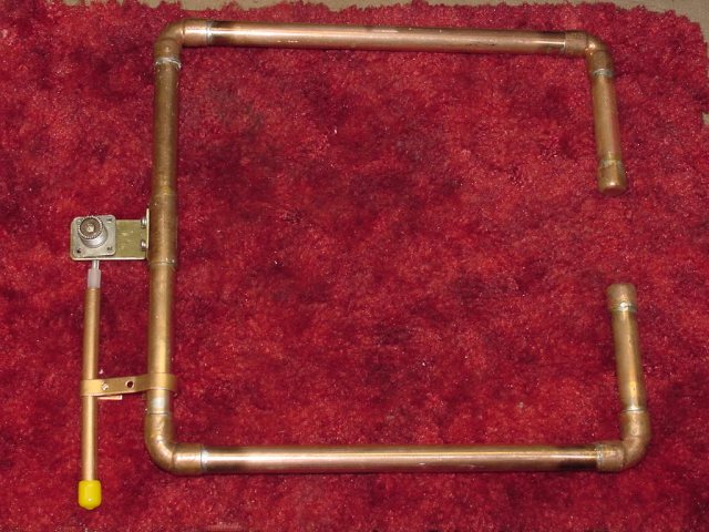 Nearly Complete
Have fun on 2 meters — Geo, K0FF
The 6 Meter Copper Loop….
Here is the parts list and dim. sheet for a 6m Square Copper Dipole, made from copper water pipe. Characteristics:
It is more or less omni-directional, and horizontally polarized.
Copper is the best possible electrical conductor at normal temperatures, next only to silver.
Copper conducts better than gold! Antenna efficiency is the RADIATION RESISTANCE of the antenna, divided by the ELECTRICAL RESISTANCE. An antenna made from copper is 1.6 times more efficient than the same antenna made of aluminum.
It presents a high angle of takeoff when mounted low, and singly (great for Es), can handle 100W. Stack two or more for extra gain if needed.
It’s just a dipole folded around on itself, and supported at the far (open) end with a plastic insulator.
“Bent Dipole” might be a good term, as a “Folded Dipole” is quite another thing.The Gamma Match: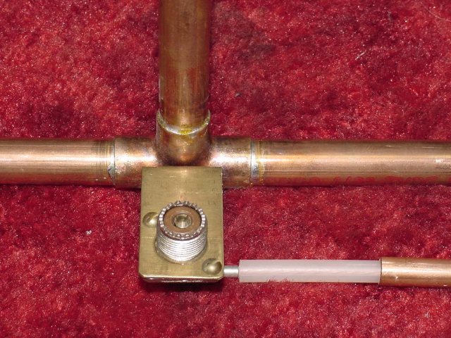
A low VSWR may be obtained by adjusting the Gamma Match shorting bracket position, and also the length of the tubing and shorting bracket. The Gamma bracket “finds” the 50 Ohm point along the element, and connects that to the Coax connector via the Gamma tube. The additional length of tube adds inductance into the circuit, and this is canceled out by the series capacitance formed between the insulated Gamma wire and the inside of the Gamma tube.
Description:
The shape is a closed 28″ square, with a mounting /support bar through the middle. This mounting bar is attached to a copper TEE at the drive end, and to a CPVC TEE at the other end. The CPVC TEE acts as support and end-insulator for the radiating element and provides a mounting point for the Butterfly.Insulator:
A large (3/4″) part is used, and adapted down to fit the water pipe, to increase its insulating qualities, as there is very high voltage at this point. A strip of brass or copper 1/2 by 3″ is screwed to the outside middle portion of the CPVC Tee, through a small center hole, and is rotated one way or the other as a resonance tuner (Butterfly). When the Butterfly is at right angles to the element, the frequency is the highest, when Parallel, it’s the lowest.
A Gamma match sets the impedance to 50 Ohms, and the Butterfly adjusts the center frequency. Center frequency is 50.00 to 50.800 with the exact dimensions shown Typically the 2:1 SWR bandwidth exceeds 500 kHz.
Mounting:
A U-bolt and saddle through the central tube provides a center mounting point. Another approach is to install a copper TEE in the center tube, with the open end down. In that open end solder a 1/2″ brass rod which has been drilled and tapped for 3/8-24.
Side mounting on a tower can be achieved by using conduit clips to fix it to a horizontal mast.
In some climates where water is a problem, drill small weep holes in the bottom corners. A spray coat of Krylon Clear Enamel will keep the copper shiny. If used mobile, you may use a colored paint, the same shade as your vehicle.
Construction:
Material:
1/2 inch Copper waterpipe:
3 ea. 27 inch piece
4 ea. 12.5 inch piece
1 ea. 13.5 inch piece 3/8 i.d. Copper refrigeration tubing (Gamma tube) *
1 ea. Brass plate 1/2″ x 3″ (Butterfly) *
1 ea. Brass plate: 1″x 2-1/4 in (to mount SO-239, Gamma rod) *
1 ea. Copper strip 3/8 x 4″ to make Gamma tube bracket *
4 ea. Copper 90 Degree elbow
1 ea. 3/4 CPVC TEE
3 ea. 3/4 to 1/2 CPVC reducer
1 ea. Copper TEE
1 ea. 11 inch piece of RG8 insides (center conductor and insulation, Discard shield and outer plastic) *
1 ea. SO-239 coax connector (with tapped mounting holes and center pin) *
1 Lot Stainless Steel and Brass screws and Hardware *
Glue two of the 12.5″ pipe sections into the CPVC reducers first, then glue the reducers into the opposite sides of the CPVC TEE.
Lay the assembly on a flat surface with the center opening of the TEE facing the middle of the antenna. This is where the first 27″ piece (mounting bar) goes in, via a reducer. On the outside edge of the CPVC TEE is where the butterfly attaches. For mobile or portable use, use 3 s.s. #6 screws through each of the CPVC TEE joints for added strength.
The rest of the antenna solders together to form a square, using the 90 degree elbows at the corners. Drill small weep holes in the bottom corners of all four 90s to let accumulated water drain out.
The brass plate is bent to form an “L” 1-3/4″ tall with a 1/2″ lip. A 5/8 hole is provided 1-1/4 inch from the bend, and an SO-239 is attached . Two small holes are drilled in the lip and the plate is mounted to the copper TEE with #6 s.s. self taping screws. Attach the center conductor of an 11″ piece of RG8 insides to the center pin (center wire and plastic dielectric only- remove and discard shield and outer covering). This is accomplished by soldering or using a screw if the SO-239 has a threaded center pin *
Slip the other end of the RG8 insides into the 3/8″copper tube 10.5″, and tap the copper tube to the radiating element 13-1/2″ from the SO-239 center, with the Gamma tube bracket.
The tap on the Gamma sets the impedance presented to the feedline. Resonance (center frequency) is adjusted by turning the butterfly.The Butterfly:
Mount 15 feet or more high, for home use, and wherever you can for mobile. An antenna like this can be mounted 3″ to 6″ above the roof of a vehicle using CPVC, PVC or acrylic spacers with suction cups.
Have fun on 6 meters Geo, K0FF
WARNING * This is antenna is an electrical conductor. Contact with power lines can result in death or serious injury. Do not install this antenna, supporting mast or tower structure near any power lines, or where they could come into contact with power lines should the antenna or structure fall.
Geo, K0FF